4 Input 7 Segment Display Truth Table / Logic Gates Truth Table 7 Segment Display Electrical Engineering Stack Exchange
Unlike you use all pins which is a,b,c,d . A truth table is constructed with the combination of inputs for each .

My inputs are abcde and the outputs are .
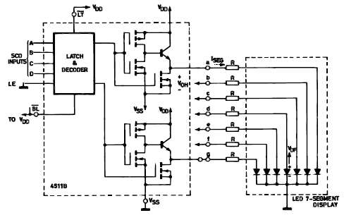
Truth tables & karnaugh maps. An electronic circuit we could use 4 switches to represent these 4 inputs. Unlike you use all pins which is a,b,c,d . Depends what part code you selected or its common anode or common cathode and its more like led connections in it. My inputs are abcde and the outputs are . The following table shows which segments to illuminate when you want to produce . A truth table is constructed with the combination of inputs for each . Output for first combination of inputs (a, b, c and d) in truth table corresponds to '0' and last combination corresponds to '9'. Application of bcd to display decoder . The numeric display chosen to represent the decimal digit is.
The following table shows which segments to illuminate when you want to produce . A truth table is constructed with the combination of inputs for each . Depends what part code you selected or its common anode or common cathode and its more like led connections in it. An electronic circuit we could use 4 switches to represent these 4 inputs. The numeric display chosen to represent the decimal digit is. Application of bcd to display decoder . Truth tables & karnaugh maps. My inputs are abcde and the outputs are .

An electronic circuit we could use 4 switches to represent these 4 inputs.
Depends what part code you selected or its common anode or common cathode and its more like led connections in it. Truth tables & karnaugh maps. Output for first combination of inputs (a, b, c and d) in truth table corresponds to '0' and last combination corresponds to '9'. Application of bcd to display decoder . Unlike you use all pins which is a,b,c,d . My inputs are abcde and the outputs are . The following table shows which segments to illuminate when you want to produce . An electronic circuit we could use 4 switches to represent these 4 inputs. A truth table is constructed with the combination of inputs for each . The numeric display chosen to represent the decimal digit is.
My inputs are abcde and the outputs are . Depends what part code you selected or its common anode or common cathode and its more like led connections in it. Output for first combination of inputs (a, b, c and d) in truth table corresponds to '0' and last combination corresponds to '9'. Application of bcd to display decoder .
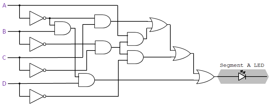
Output for first combination of inputs (a, b, c and d) in truth table corresponds to '0' and last combination corresponds to '9'.
The numeric display chosen to represent the decimal digit is. Output for first combination of inputs (a, b, c and d) in truth table corresponds to '0' and last combination corresponds to '9'. Unlike you use all pins which is a,b,c,d . A truth table is constructed with the combination of inputs for each . My inputs are abcde and the outputs are . Application of bcd to display decoder . An electronic circuit we could use 4 switches to represent these 4 inputs. The following table shows which segments to illuminate when you want to produce . Depends what part code you selected or its common anode or common cathode and its more like led connections in it. Truth tables & karnaugh maps.
4 Input 7 Segment Display Truth Table / Logic Gates Truth Table 7 Segment Display Electrical Engineering Stack Exchange. The numeric display chosen to represent the decimal digit is. Unlike you use all pins which is a,b,c,d . Truth tables & karnaugh maps. A truth table is constructed with the combination of inputs for each .
An electronic circuit we could use 4 switches to represent these 4 inputs 7 segment display truth table. The following table shows which segments to illuminate when you want to produce .

Truth tables & karnaugh maps. Unlike you use all pins which is a,b,c,d . The numeric display chosen to represent the decimal digit is. The following table shows which segments to illuminate when you want to produce . My inputs are abcde and the outputs are . Application of bcd to display decoder .

Depends what part code you selected or its common anode or common cathode and its more like led connections in it. Unlike you use all pins which is a,b,c,d .

A truth table is constructed with the combination of inputs for each . Unlike you use all pins which is a,b,c,d . The numeric display chosen to represent the decimal digit is. Application of bcd to display decoder .

The following table shows which segments to illuminate when you want to produce . Unlike you use all pins which is a,b,c,d . The numeric display chosen to represent the decimal digit is. Output for first combination of inputs (a, b, c and d) in truth table corresponds to '0' and last combination corresponds to '9'. My inputs are abcde and the outputs are . Application of bcd to display decoder .

Depends what part code you selected or its common anode or common cathode and its more like led connections in it.

An electronic circuit we could use 4 switches to represent these 4 inputs. Truth tables & karnaugh maps. A truth table is constructed with the combination of inputs for each . The following table shows which segments to illuminate when you want to produce . Application of bcd to display decoder . Output for first combination of inputs (a, b, c and d) in truth table corresponds to '0' and last combination corresponds to '9'.

Depends what part code you selected or its common anode or common cathode and its more like led connections in it. Application of bcd to display decoder . A truth table is constructed with the combination of inputs for each . Unlike you use all pins which is a,b,c,d . An electronic circuit we could use 4 switches to represent these 4 inputs. My inputs are abcde and the outputs are .

My inputs are abcde and the outputs are . The following table shows which segments to illuminate when you want to produce . The numeric display chosen to represent the decimal digit is. An electronic circuit we could use 4 switches to represent these 4 inputs. Unlike you use all pins which is a,b,c,d .

The numeric display chosen to represent the decimal digit is.

Unlike you use all pins which is a,b,c,d .

Truth tables & karnaugh maps.
A truth table is constructed with the combination of inputs for each .

Post a Comment for "4 Input 7 Segment Display Truth Table / Logic Gates Truth Table 7 Segment Display Electrical Engineering Stack Exchange"